


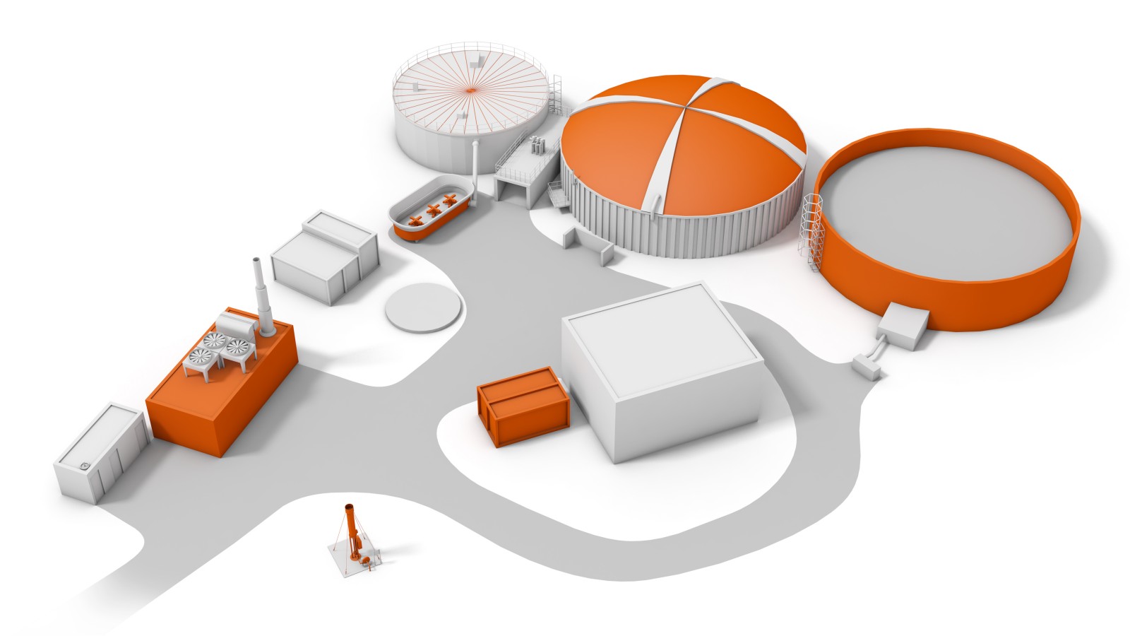
Aerial view of the Číčov biogas plant
The Číčov biogas plant lies to the north of the village of the same name, next to an agricultural establishment. Behind the gate on the access road to the biogas plant, you can see a CHP unit (Combined Heat and Power unit) and a flare for disposal of residual gas on the left. Behind the green control centre building and the equipment shed are the most noticeable parts of the biogas plant – the screw feeder trough, the first digester, the second digester (with a roof membrane) and the final storage facility.
In addition to the structures of the biogas plant itself, the whole aerial view is dominated by the seemingly endless belt of the Brdy forests in the north, east and south. Kokšín hill (684 m), hiding the ruins of a 15th century castle, rises from it on the south.
In fine weather, the south-westerly direction offers a rather impressive panorama framed with the view of Bohemian and Bavarian forest summits.
In the east lie the village of Hořice and Trokavecká skála (706 m above it).
In the northwest, above Číčov, the horizon is filled by Hájek hill (575 m).
Watch a video of the construction and operation of a bio-gas station.
CHP unit
The CHP unit (Combined Heat and Power unit) is used to convert biogas energy into electric power. Consisting of a combustion engine, the unit is supplied with purified gas from the digester. First, the gas passes through a condensate shaft where water is separated by condensation, and it then travels through a dehydration plant that dries the gas and removes residual water. Only after it has been purified completely it is supplied to a compressor where it is compressed and fed to the engine.
Twelve-cylinder Jenbacher engine
This heart of the entire biogas plant in Číčov is fitted with a twelve-cylinder Jenbacher engine and provides 40.4% electrical efficiency and 42.5% thermal efficiency.
Gas that had about 42 °C when removed from the digester is supplied to the engine at 5 °C.
When the biogas plant’s engine is not running, any generated excess biogas is burnt in the gas burner, called the flare. This is used for engine shutdowns.
On the “square” in the middle of the site
Biogas plants are modern and clean facilities that are normally operated in the Czech Republic and abroad. They handle a wide variety of materials or waste organic matter through the process of anaerobic digestion (microbial disintegration of organic matter in the absence of air) in closed reactors. The result of the process is biogas, which is currently used mostly for the production of electricity and heat, and the digestate, specifically its solid constitute the separate, which can be used as high-quality fertiliser (like compost).
The plant located at the Brdy foothills in the outskirts of Číčov near Spálené Poříčí enables electricity generation for more than 1,000 households year-round. In Číčov, the “fuel” is cattle slurry and energy crops. In the process of fermentation, they produce biogas with a high methane content. The methane is then used as fuel for electricity generation.
| Parameters of the Číčov biogas plant | |
|---|---|
| Installed capacity | 526 kW |
| In operation | 7 750 hours a year (i.e. almost 90% of the standard year) |
| Raw materials | Cattle and pig slurry, maize silage, haylage |
| Electrical efficiency | 40,4 % |
| Delivered electricity | 3,372 GWh a year (i.e. covering the consumption of about 1,000 households) |
| Digesters | Total volume 2 958 m3 |
| Gas storage | Volume 1 020 m3 |
| Sludge tank | Volume 2 000 m3 |
Biogas plants mostly operate automatically. Most significantly, it is important to ensure the regular supply of input materials and to dispose of the digestate, the residue of the fermentation process, during the season. Input substrate includes slurry as well as maize silage, haylage and other suitable biomass. Depending on their quality, about 16-55 tonnes of input materials are needed every day, totaling approximately 20,000 tonnes per year.
The first material to “start up” the Číčov biogas plant was delivered in mid-June 2011. The start-up required 450 m3 of slurry and 160 m3 of inoculum (reacting substrate from another biogas plant).
The whole biogas plant covers an area slightly bigger than 1 ha, including the access road.
Screw feeder
Every hour, a portion of the daily volume of biomass, i.e. an aliquot of 22 tonnes, is put into the screw conveyor feeder (with amber walls). The feeder disintegrates the biomass using three rotating screws and a conveying screw takes it into the first digester with a fixed concrete ceiling and a capacity of 870 m3. Here the material is left in the absence of air for 20 days. Agitators inside the tank keep the mass agitated to let biogas freely bubble towards the digester’s ceiling, where it is collected. Heated walls keep the temperature at 42 °C.
Second digester
After being kept for 20 days, the digestate is pumped by the central pump into the second digester with a total volume of 2,088 m3. Here it matures a further 25 days for the total of 55 days needed to create ideal biogas. Biogas is gas produced during anaerobic digestion of organic materials, consisting mainly of methane (CH4) and carbon dioxide (CO2). The individual tanks consist of several concrete blocks 6 metres high (the total height of a digester including its underground parts and roof is about 10 metres). Walls are 31 cm thick, including heat insulation. The two-membrane biogas storage has a volume of 1,020 m3 and forms the roof of the second digester. Air is permanently blown into the upper jacket, filling the space between the membranes and creating slight overpressure under the lower membrane where biogas is accumulated. Biomass is sealed with a special canvas in the second digester; there is an air pocket above it and another canvas covering the whole tank. The tanks are stabilised by ropes pre-tensioning the structure on the outside.
Final storage
Processed biomass is either solid (separate) or liquid (fugate). Separation into the solid and liquid components is carried out using a separator. The fugate is used to dilute the reacting substrate if necessary to maintain the correct dry matter content in the digesters. When removed from the digesters, the solid separate can be used for fertilising as an additive to compost or burnt as biomass in pellets. The liquid component is discharged into an open storage pit (final storage facility) with a volume of 2,000 m3, which is approximately emptied once every 3 months.
Flare
The flare, a nozzle serving to safely burn excessive gas, burns 150-250 m3 of gas per hour at 10-50 mbar when the biogas plant’s engine is not running. The flare is 4.8 m high.
Machine room, central pump
The central pump primarily transfers the digestate from the first digester to the second digester. It can also be used in the opposite direction if the digestate in the first digester needs to be diluted. The digestate agitated in the second digester has lower dry matter content than that in the first digester.
Digesters
The view from the roof of the first digester begins our excursion, which also describes the production chain in a biogas plant.
Screw feeder
Every hour, a portion of the daily volume of biomass, i.e. an aliquot of 22 tonnes, is put into the screw conveyor feeder (with amber walls). The feeder disintegrates the biomass using three rotating screws and a conveying screw takes it into the first digester with a fixed concrete ceiling and a capacity of 870 m3. Here the material is left in the absence of air for 20 days. Agitators inside the tank keep the mass agitated to let biogas freely bubble towards the digester’s ceiling, where it is collected. Heated walls keep the temperature at 42 °C.
Second digester
After being kept for 20 days, the digestate is pumped by the central pump into the second digester with a total volume of 2,088 m3. Here it matures a further 25 days for the total of 55 days needed to create ideal biogas. Biogas is gas produced during anaerobic digestion of organic materials, consisting mainly of methane (CH4) and carbon dioxide (CO2). The individual tanks consist of several concrete blocks 6 metres high (the total height of a digester including its underground parts and roof is about 10 metres). Walls are 31 cm thick, including heat insulation. The two-membrane biogas storage has a volume of 1,020 m3 and forms the roof of the second digester. Air is permanently blown into the upper jacket, filling the space between the membranes and creating slight overpressure under the lower membrane where biogas is accumulated. Biomass is sealed with a special canvas in the second digester; there is an air pocket above it and another canvas covering the whole tank. The tanks are stabilised by ropes pre-tensioning the structure on the outside.
Flare
The flare, a nozzle serving to safely burn excessive gas, burns 150-250 m3 of gas per hour at 10-50 mbar when the biogas plant’s engine is not running. The flare is 4.8 m high.
Control room
The control centre of the entire biogas plant is the control room, which is located in a room on the ground level next to the equipment shed. Two control monitors display information from all parts of the biogas plant here. Biogas plant operators use the monitors and control panels to check all current indicators and values relating to electricity generation.
Help
Left-click and drag to choose the viewing angle, or use the keyboard.
| Go to the main homepage | |
| Go to the power plant’s homepage | |
| Show information about the viewed part of the excursion | |
| Show your position in the power plant | |
| Show the thumbnail gallery | |
| Zoom in | |
| Zoom out | |
| Pan to the left | |
| Pan to the up | |
| Pan to the down | |
| Pan to the right | |
| Help | |
| Enter full screen mode |