


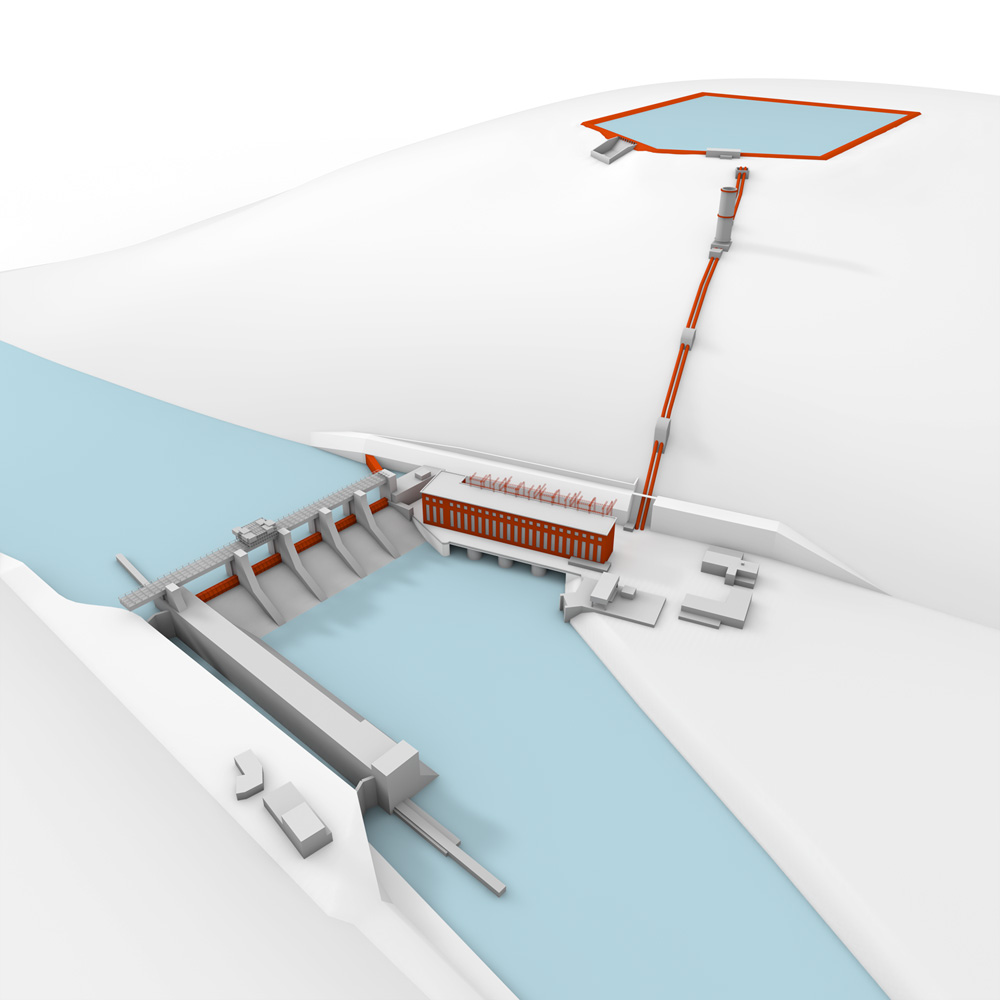
Aerial view of the run-of-river and pumped-storage hydro plants
The Štěchovice waterworks was built in 1938 to 1947. The concrete dam with granite revetment is 22.5 m high and 120 m long. This waterworks includes a lock chamber, which overcomes the difference of 19.10 m between the lower and upper water levels and is unique in Central Europe. The dam has five gated spillways. The capacity of the spillways is 2,400 m3/s but they could safely withstand such catastrophic floods as in 2002. The Štěchovice waterworks includes two power plants – run-of-river and pumped storage. The upper reservoir of the pumped-storage plant is located on the Homole hill above the dam. Water is pumped to it through a double pipeline. Water is pumped upwards when there is an excess of electricity and released down to the turbine to generate electricity when there is lack of it. After a reconstruction in 1996, the pumped-storage plant has a capacity of 45 MW and the run-of-river plant 22.5 MW.
Aerial view
This shows the whole power plant site including the upper reservoir and the town of Štěchovice. The run-of-river plant’s reservoir is 9.4 km long and ends at the stilling pool of the Slapy power plant. It holds 11.2 million m3 of water and serves mainly to equalize the varying outflow of the Slapy peaking power plant. Together with the Vraný reservoir, it equalizes the whole Vltava cascade outflow. The operation of the Štěchovice power plants is managed directly from the Vltava cascade control centre.
The fascinating panorama lets you fly freely through the air and shows the Štěchovice dam structures and the two power plants as well as virtually tens of square kilometres of the Central Bohemian landscape along the Vltava. Besides the upper reservoir of the pumped-storage plant at Homole beneath the peak of Chlum (448 m), you can look upstream along the Vltava in the St John’s Rapids area, across the mountain Severní varta (429 m), up to the bays of the Slapy reservoir.
North-eastwards, behind Třebsín, you can clearly see the valley of the Sázava, whose junction with the Vltava between Hradišťko and Davle can be imagined northwards. Spreading before you is the whole town of Štěchovice with its landmark Edvard Beneš Bridge across the Vltava and the valley of the Kocába winding towards the Vltava from the west.
Dam
Bottom outlet
There is a bottom outlet in the middle of the dam, which was used to empty the reservoir when the power plant was built. The outlet is in the original river channel. The reservoir level is regulated by the operation rules of the Vltava River Authority.
Bulkhead gates
In extreme conditions, the dam bulkhead gates may discharge up to 2,400 m3 of water. However, the flow during the 2002 flood was 3,200 m3 of water. The gates are sealed with rubber.
Run-of-river turbine building
Like a standard run-of-river plant, the medium-pressure power plant is fitted with 2 Kaplan turbine assemblies. It includes a 110kV switchyard and unit transformers.
Diagram of the Štěchovice I hydro power plant.
The turbine building is equipped with two Kaplan turbines with a capacity of 11.25 MW each. Each turbine is connected by a common shaft to a generator, whose red housing can be seen in the turbine building.
| Štěchovice production unit | |
|---|---|
| Installed capacity | 2 x 11,25 MW |
| Year of commissioning | 1943 - 1944 |
| Turbine type | Kaplan |
Generators
A generator consists of a stator and a rotor; it generates three-phase alternating current. The rotor is driven by a turbine and current is drawn from the stator and supplied to the switchyard. Here the generator output voltage of 10.5 kV is transformed into 110 kV. The generator frame and bearings, including the runners, are originals from 1947. There have been upgrades but the original structure is still in use.
Oil inspection window
Before the operation was automated, lubricating oil flowing back from the generator’s axial thrust bearing and radial guide bearings was checked through this inspection window. Continuous oil flow was monitored.
Turbine governor – hydraulic part
The governor cabinet is used to regulate oil pressure in actuators that control the opening of wicket gates, regulating the amount of water allowed through. Blades on the runner are adjusted depending on the angle of the wicket gates to achieve optimum performance of the Kaplan turbine. Oil in the governor is pressurized to about 20 atmospheres.
Governor pumping set (GPS)
The governor pumping set (GPS) supplies pressurized oil for the turbine control system, driving the actuators of the wicket gates and the runner blades. The governor oil is stored in the GPS tank and filters are included in the pump circuit to remove mechanical impurities. The governor oil has to be very pure. The GPS air chamber (the blue cylinder behind the governor cabinet) holds enough pressure energy to close the turbine in case of emergency even if the power supply of the GPS pumps is lost.
The oil system of not only the GPS but of the entire power plant is strictly controlled and closely monitored to prevent the oil from leaking into water and polluting the environment.
Run-of-river plant’s auxiliary plant room with water treatment plant and oil systems for plant bearings
Draft tube emptying pump
Water is pumped out of the blocked and secured turbine using the draft tube emptying pump during maintenance shutdowns, approximately once in two years. The turbine is blocked from both sides, water is pumped off to the river and the pump uses a level sensor to monitor the level of water that may have leaked through the provisional gate.
Unit for all lubricating oils
The lubricating oil unit is used to filter and pump oil to the bearings of the generator and the turbine. The generator and turbine rotate in a set of four bearings, one axial and three radial bearings. The axial bearing is what the whole generator is suspended from. The radial bearings keep the assembly strictly vertical and are located above the generator, under the generator and in the turbine.
Located next to the unit is the water system that is used to cool the oils supplied to the generator bearings and to cool generator stator windings. Water is pumped from the river through filters to remove undesirable impurities and only then supplied to plate coolers.
Turbine and generator shaft coupling
Turbine cover area, turbine and generator shaft coupling
Below the generator is the turbine cover. A fast coupling of the rotor shaft and the turbine shaft is located there. The coupling is also a hydraulic actuator that controls the angle of propeller blades. The turbine’s guide radial bearing is located under the floor. The shaft is partially covered with red covers. There is a carbon seal under the bearing, which both prevents water from leaking along the runner and lets a small amount of water seep through to prevent a shaft jam. Excessive water is removed by two pumps. A third pump is used to remove leaked oil. Valves (blue) let air into the turbine during an emergency shutdown to prevent negative pressure in the draft tube.
The turbine cover includes 20 wicket gates that are controlled by pressurized oil using actuators. The entire mechanism (a regulating ring and levers) thus converts the linear motion of the actuators into circular motion to ensure identical opening and simultaneous movement of the wicket gates.
The runner actuator (large cylinder) is a piston that is controlled by pressurized oil; runner blades move (close or open) depending on where the oil is supplied to – either above or under the piston. A rod is attached to the underside of the piston, running through the lower hollow shaft to the runner and rotating the turbine’s moving blades. The mechanism thus converts linear motion into the circular motion of the blades.
House generator
The house generator served as a starting system for the turbine generators in the event of a power cut. A DC drive was used to generate energy to pressurize the oil that could control this small turbine. The house generator then supplied electricity to start up the main generating set, making it able to supply power to the 110kV switchyard. The house generator was damaged beyond repair during the 2002 flood, so it was replaced with a diesel generating set that is now located in the 110kV switchyard. The generator’s inlet and outlet were sealed with concrete.
A view across the wicket gates to the upper part of the Kaplan runner
The Kaplan turbine’s runner is located in an enclosed round space that is not walled in to allow replacing the entire turbine if needed. If it is changed, the entire plant above it, including the generator, will have to be dismantled. The runner as a whole has not been changed yet; the cladding is original and parts of the runner have been renewed several times. The spiral case adapter has been replaced.
Spiral case of the run-of-river plant
Water is delivered to the turbine by a penstock that forms a spiral (scroll) around the turbine. The spiral gets tighter and tighter, accelerating the water. The spiral directs water to the wicket gates that are used to regulate the water supplied to the turbine runner. Water pushes against the runner blades, runs past the runner hub nose cone and from there it is discharged to the draft tube and then to the river downstream of the dam. Under ideal conditions, this path is passed by 80 m3 of water per second.
Runner nose cone
The wooden platform is here to allow inspection – during operation, there is empty space under the nose cone through which water falls down into the draft tube.
Control room
The Štěchovice power plants are unmanned but under three-level supervision. The first level of supervision is right at the machinery. The second level of supervision is provided by a central control room, which ensures comprehensive monitoring for the power plant using an SAT control system, a security system and a CCTV system. The third, highest level is the Vltava cascade control centre, which operates 24/7 and controls the entire Vltava cascade right from Štěchovice.
Museum
The Control Centre shares the room with a small museum that shows the history and interesting facts relating to the Štěchovice power plant and waterworks. Authentic photographs take the visitors decades back in time, letting them witness almost first-hand the great changes to the Vltava valley upstream of Štěchovice.
The museum’s display cases preserve unique historic exhibits not only for generations of excited eyewitnesses and enthusiasts, while the side window offers a romantic view of the great hall of the run-of-river plant’s turbine building.
Switchyard, power system protection and metering control room
From the central control room you can enter a room with digital protective devices for medium-pressure units, HV substations and SAT control computers, which safeguard the operation of the power plant as a whole. You can also see cabinets with electricity meters for accurate metering of electricity supplied to the grid.
110kV switchyard
The 110 kV switchyard is used for power output as well as transformation. The run-of-river plant’s turbines work with 10.5 kV AC voltage, those of the pumped-storage plant work at 13.8 kV. Here the voltage is transformed into 110 kV, which is then distributed through outgoing lines to the Slapy power plant, Týnec nad Sázavou, the Vrané power plant and the Chodov switchyard in Prague.
Gen-set
The switchyard includes a gen-set that can supply the power plant in case of a blackout. This replaced the house generator.
Ventilators
Transformers become hot in operation, heating the oil that serves as an insulating medium in them. The oil flows through coolers that are cooled by ventilators.
Run-of-river plant intake, trash rack cleaning machine
Coarse rack
The coarse rack consists of a system of tubing that runs almost to the bottom of the reservoir and is about 15 metres long. It captures large debris (planks, trees, dead animals, …). Water flows through the coarse rack to the intake area, where smaller debris is removed, and then it is supplied to the generators.
Fine rack
Smaller debris is removed from water at the fine rack by a cleaning machine. The fine rack consists of steel sections spaced 5 cm apart. Controlled by power plant operators, the cleaning machine uses a rake to remove smaller debris from water and throw it into a prepared container. When full, it is removed for environmentally friendly disposal of the debris.
Stop log handling crane
The fine rack cleaning machine is combined with a stop log handling crane that is used for handling when shutting off the turbine penstock. The crane lowers four steel plates with rubber seals into their place at the beginning of the penstock. This prevents water from entering the turbine. The remaining water is pumped off and people can enter the space.
Emergency gates
The blue hydraulic cylinders above the turbine intake are actuators for emergency gates. These are 60-tonne panels. In the event of a mechanical failure, the panel lowers, reaching the bottom within 40 seconds and shutting off water. It takes 10 minutes to raise it again.
Turbine control room of the Štěchovice II pumped-storage plant
The Štěchovice II pumped-storage hydro power plant with a head of up to 220 m and a 500,000 m3 artificial reservoir on the Homole hill was put into operation in 1947. For its time, the pumped-storage hydro power plant was fully automated and waste heat from its cooling system was used to heat water in a swimming pool nearby, among other things. It had generated 1,650,000 MWh of mostly peak-load energy until February 1991, when it was shut down for its obsolescence. A new, modern PSH plant was built in 1992–1996, making use of the original upper reservoir at Homole and, to a large extent, the original steel penstocks (pipe diameter 1.7 to 2 m, length 590 m) and some power distribution systems. The original two 21MW assemblies were replaced with one, having a reversible Francis turbine with a 2.2 m runner, maximum throughput of 24 m3 of water per second and a 45 MW motor generator. The assembly is located in an underground plant room, about 45 m deep.
Diagram of the Štěchovice II hydro power plant
| Štěchovice II production unit | |
|---|---|
| Installed capacity | 1 x 45 MW |
| Year of commissioning | 1996 (rebuilt) |
| Turbine type | Reversible Francis design |
Generator floor of the pumped-storage plant
Generator
The pumped-storage power plant has a shaft design. The lower part of the shaft contains the generator and the main ball valve for water inlet.
When pumping water to the upper reservoir, the reversible turbine switches to a pumping mode. First the unit has to be started as an asynchronous motor with the pump without water, then water is supplied to the runner, pressure at the turbine is equalized with pressure in the penstock, and the pump takes off power and starts pumping upwards.
Water management
The lower part of the shaft also includes a water management system that is used to filter river water for cooling the unit bearings, the unit generator and shaft seals.
Ball valve at water inlet
The penstock ball valve is controlled by a hydraulic actuator.
Generator brush gear
The floor with the generator brush gear is located above the generator. The gear is connected to a thyristor exciter. The rotor is supplied through the rings and brushes of the brush gear. Power from the stator is delivered to the unit substation, located in the upper part of the shaft.
The ball valve can be seen on the floor below.
Pumped-storage plant’s upper reservoir
The artificial reservoir at Homole hill above the power plant serves as water storage for the high-pressure pumped-storage plant. It is a concrete pool with a clay bottom and a capacity of 500,000 m3. A minimum water level must be maintained during draining – the reservoir may never be emptied completely to prevent the clay bottom from drying and cracking, losing its permeability. There is a “bowl” right at the pipe inlet, a hollow where the last water must be held. When the plant is shut down for a longer period, the reservoir must have enough water to perform the first starting cycle by letting the water down. Pumping operation is resumed then.
The first major repair of the upper reservoir took place during the reconstruction after 1991. The repair involved joints, which erode due to wetting. During the repair, the clay bottom proved to be very tight with minimum seepage.
Emergency spillway
The safety spillway is there in case the automatic system fails to stop the pumping process when water is pumped up to the reservoir. There would be a spillover at the spillway, which would take the excessive water down to the Vltava. Measuring probes (pipes) on the bottom of the spillway are used to measure reservoir seepage. There have been two spillovers during the power plant’s existence. In 1991, water was discharged from the reservoir in a controlled manner using a suction pump and gravity. The pumping took approximately two months.
The priming pump was also used during the 1991 reconstruction. The priming pump serves to fill the reservoir if there is no water at all in it. Water is then pumped from the lower part of the power plant to the reservoir. It takes about three to five months of pumping until the reservoir is full.
Intake plant room of the pumped-storage plant
Here are the upper ends of the pipes that connect the upper reservoir and the power plant downhill. Penstock flap valves are kept up by hydraulics. During a shutdown, they come down and the pipe cross-section is blocked. They serve as safety valves. There are also emergency flap valves, with manual control, that are used to shut off water if the safety valves need to be repaired and for safe work in the penstock.
Surge chamber
The surge chamber at Homole was built during the major reconstruction of the pumped-storage power plant in 1991–1996. During the reconstruction, the high-pressure hydro power plant’s two generators were replaced with one advanced generator and a surge chamber was built in the upper part of the penstock. The surge chamber is a safety device consisting of an open 35m high cylinder. From the top you can see the free water level which is at the same height as the level in the upper reservoir.
The chamber is fitted to the piping and compensates pressures/surges occurring in the pipeline during pumping and when the turbine is being shut down. When the pump stops pumping, the water jet breaks off and water pushes down, creating a great surge. To prevent damage to the piping, the surge is dampened by the surge chamber.
Lift
An operator lift runs along the pipeline from the power plant up to the surge reservoir.
Information centre
The Štěchovice power plants are open for visitors, by arrangement, on weekdays and weekends throughout the year. The information centre includes educational panels, models and films to familiarize you with the power plant equipment and neighbourhood.
Help
Left-click and drag to choose the viewing angle, or use the keyboard.
| Go to the main homepage | |
| Go to the power plant’s homepage | |
| Show information about the viewed part of the excursion | |
| Show your position in the power plant | |
| Show the thumbnail gallery | |
| Zoom in | |
| Zoom out | |
| Pan to the left | |
| Pan to the up | |
| Pan to the down | |
| Pan to the right | |
| Help | |
| Enter full screen mode |